If you connect the LCD TV to your computer, you can watch movies downloaded from the network or DVDs (without a DVD player), as well as view photos and slide shows on big screen and finally, no one can forbid you to surf the Internet right from the couch.
In addition, large plasma panels connected to a PC are used as display and exhibition equipment. To do this, you just need to correctly connect both devices.
In order to realize this possibility, we need to connect the computer and the TV using a special cable. The type of cable depends on which TV and computer connectors will be used for switching. Therefore, we first determine what connectors the TV and computer are equipped with.
The video card is responsible for outputting the video signal from the computer. Its connector is very easy to find: your monitor is connected to one of them.
TV connectors should be looked for on its rear panel, on the side, and sometimes even in front.
What are the connectors for a video card?
D-Sub (VGA)- a connector to which an ordinary monitor is connected, such a connector is on most video cards, except for latest models that use more modern interfaces. D-Sub was also called "VGA interface".
An analog signal is transmitted via the VGA interface.

DVI-I- an improved interface that serves both to connect analog and more modern digital monitors. As a rule, on a DVI-I video card, the connector is adjacent to a traditional VGA interface, or the video card is equipped with two DVI-I connectors, and in the kit there is an adapter from DVI-I to the good old D-Sub.

S-video(English) separatevideo) - The S-Video analog signal connector, often incorrectly referred to as Super-Video and S-VHS, is mainly used to output the image generated by the computer's video card, as well as the video signal from camcorders or gaming devices to consumer televisions or similar home video equipment.
This connector is widely used among "non-computer" video equipment and provides a fairly high-quality video signal transmission.
Significant advantage this connection(compared to the simplest composite, on one "tulip") is that the luminance signals ( intensity,Luminance,Y) and chromaticity ( color,Chrominance, C) images are passed separately. Thus, they are never in composite mode and do not appear on the vertical edges of multi-color areas of the image. cross brightness. In addition, there is no need to filter the luminance circuits on the TV to get rid of the chrominance of the signal, which allows you to increase the bandwidth and, accordingly, the horizontal resolution of the screen. Of course, the resolution is still limited to the kinescope CRT, but this is a clear improvement.
Modern computer video cards use several variants of the S-Video connector with a different number of pins. As a rule, the output (or video input-video output) of the video signal from the video card with the help of an adapter is carried out to the component output. The 4-pin S-Video connector is the same as the mini-DIN connector for connecting a Mac keyboard, but this is only a mechanical match.
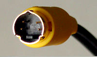
Appearance and pin numbering of the 4-pin S-Video connector.
Pin Description 4 PIN S-Video
|
Output No. |
Purpose |
|
|
Luminance (Y) signal |
||
|
Color (C) signal |
Nest7-pin S-Video
View from the socket and pin numbering of the 7-pin S-Video connector.
|
Output No. |
On ATI video cards |
On nVidia graphics cards |
On thelaptopslg,Intel, Apple Power Macintosh 6100AV/7100AV/8100AV AndApple PowerBook |
|
Luminance (Y) Common |
|||
|
Common color (C) signal wire |
|||
|
Luminance (Y) signal |
|||
|
Color (C) signal |
Color (C) signal or Component (PR) red |
||
|
Composite (V) "Video" signal common |
composite signal (V) "Video" or component (PB) blue (for LG laptop) |
||
|
Not involved |
Composite (V) "Video" or Component (PB) Blue |
Composite "Video" signal common wire (for LG laptop) |
|
|
Composite signal (V) "Video" |
Not involved |
||

HDMI– a digital interface used in a high-definition television system. Provides the highest quality image and simultaneous transmission of video and audio.
What cables are needed:

D-SUB cable for connecting a monitor to a computer, a monitor to a laptop, a projector to a laptop, or any video device with a D-Sub connector to a signal source with a D-Sub connector.

S-Video cable - when using this connector, both on the TV and on the video card, there is no need to use special adapters.
It is also possible to use a D-Sub (VGA) S-Video adapter.

Cable that turns D-SUB (VGA) into an RCA tulip and into S-video
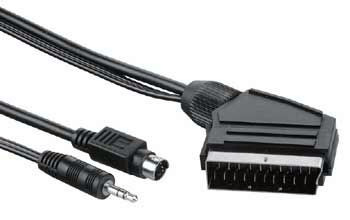
SCART - S-Video cable - providing simultaneous transmission of video and audio signals. Usually used to connect a video player, but can also be used for a computer. In this case, either a VGA-SCART or S-Video-SCART cable is required. You can get by with similar adapters, which, by the way, in addition to the video input, can also have an audio input for connecting sound.

A DVI to HDMI cable is recommended if your video card has a similar connector, a simple HDMI cable is required for this. As an option - an inexpensive cable adapter from DVI to HDMI,
In addition, the TV may have a standard D-Sub (VGA) connector for monitors and a DVI-I interface. This option simplifies the connection task as much as possible, because it does not require additional adapters.
- Digital video outputs are best for connecting a PC or laptop to a TV. The best choice is to connect using HDMI. As a rule, a modern flat-screen TV has an HDMI connector.
- The DVI connector is much more common than HDMI and carries the same video signals. Using the appropriate adapter or cable, you can connect the DVI output on your computer to the HDMI input on your TV.
- It is desirable that the connectors of the video card (computer) and the TV match. DVI-I > DVI-I, S-Video > S-Video, etc. This will avoid the problem of finding all kinds of adapters. In addition, the transformation from one interface to another may reduce the quality of the picture.
- If direct connection is not possible, use adapters. The following connection types are considered acceptable: D-Sub (VGA) - DVI-I, D-Sub (VGA) - SCART, S-Vide about- SCART, DVI-I - SCART.
Don't skimp on connecting cords. Cheap cables have low noise immunity, which reduces image quality .
Connecting a TV in Windows XP
Waiting for the download operating system, right-click on an empty space on the desktop and select Properties. In the window that opens, click on the Settings tab. Next, you need to select the second monitor (marked with the number 2), and check the box "extend the desktop to this monitor."
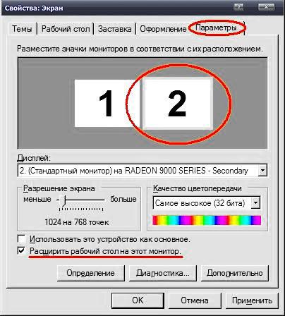
You can see the result on the TV screen by selecting the channel " Video". There may be several of them, but one of them is exactly the one to which information is transmitted from the computer.
To watch movies or photos on the TV screen, just drag the window of the video player or image viewer to the second desktop, that is, to the TV screen. After that, you can expand the movie or photos to full screen and enjoy watching.
In the desktop settings, you can set the main monitor. If the TV is selected as the main monitor, then the Start menu, desktop shortcuts, etc. will be displayed on it. This option is convenient when the TV is used as a monitor constantly or often enough.
For more detailed information on "fine" settings of the TV, you can refer to the instructions for using the video card.
In addition, there are special programs for video cards from various manufacturers that allow you to quickly and conveniently set up a video card to work with a TV. These programs allow you to select the type of signal, resolution, image size, adjust the brightness and, rather, are intended for "advanced users".
One of these programs is MonInfo is located .
We will not consider in detail the possibilities of these programs, because even standard Windows methods you can get what you want.
Connecting a TV as a second monitor

If the video card has a TV-out (S-Video connector), and the TV has a SCART-input, then you can use an adapter cable.


S-Video connectors 7-pin and 4-pin S-Video to SCART adapter
EUROPEAN PLUG SCART
|
Cont. |
Purpose |
signal level, circuit resistance |
|
right channel audio output (mono) |
V = 0.2-2.0 V , R<1кОм |
|
|
right channel audio input (mono) |
V \u003d 0.2-2.0 V, R> 10kOhm |
|
|
left channel audio output |
V = 0.2-2.0 V , R<1кОм |
|
|
common audio signal wire |
--- |
|
|
common signal wire "BLUE" |
--- |
|
|
left channel audio input |
V \u003d 0.2-2.0 V, R> 10kOhm |
|
|
signal input/output "BLUE" |
||
|
TV/VIDEO switching voltage input/output |
V off = 0 - 2.0 V , V on. = 9.5 - 12V , |
|
|
common signal wire "GREEN" |
--- |
|
|
second input channel |
not used on some devices. |
|
|
signal input/output "GREEN" |
peak-to-peak 0.7 V V DC \u003d 0-2.0 V, R \u003d 75 Ohm |
|
|
first input channel |
not used |
|
|
common signal wire "RED" |
--- |
|
|
common wire of the first data input channel |
not used |
|
|
"RED" signal input/output |
peak-to-peak 0.7 V V DC \u003d 0-2.0 V, R \u003d 75 Ohm |
|
|
TV/RGB switching voltage input/output |
V off = 0 - 0.4 V , V on. = 1.0 - 3.0 V , R input. = 75 ohm |
|
|
composite video common |
--- |
|
|
TV/RGB switch voltage common wire |
--- |
|
|
positive polarity video output |
||
|
positive polarity video input |
1.0 Vp-p, Vdc \u003d 0-2.0 V, R \u003d 75 Ohm |
|
|
frame |
--- |
Norm for all video inputs and video outputs:
Signal swing 0.7V,
DC component 0-2V,
Resistance 75ohm.
Zero logic level voltage for control input (terminal 8) no more than 2V, logical unit, - from 9.5 to 12V.

Adapter "S-Video - tulip": "grounds" are connected to the "ground" of the tulip, and the brightness signal Y mixed with a shunted 470 pF chrominance capacitor C , is connected to the central core.
Audio signal
Having decided on the video, let's move on to the sound. On computer sound cards, as a rule, a 3.5 mm TRS connector (miniJack) is used. On a TV, the audio input can be made in the form miniJack, TRS 1/4 "(Jack) or RCA audio ("tulips"), that is, you may need the appropriate cables or adapters. Finding them is not a big problem, the main thing is to determine exactly which ones connectors used on your TV.

3.5 mm TRS connector (miniJack)
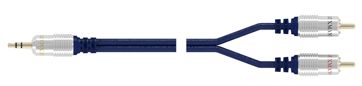
Typical MiniJack to RCA cable
When connecting a TV via a SCART interface, special adapters are used from audio + video signal to SCART. For example, it is possible that the video signal is transmitted from the S-Video connector to the SCART connector through an adapter, and a miniJack cable is connected to the RCA connectors in the same adapter.
If you have a separate audio system connected to your TV, then it is advisable to transmit the sound directly to it.
All connection operations must be carried out with off equipment.
When the right cables are inserted into the right connectors, you can turn on the computer and TV and proceed to the software setup.
According to materials:
ComputerBild №06/2008
http://tv-vision.info/
We display the image from the computer to the TV
In order to connect a computer to a TV (we are talking about television equipment produced over the past few years, and not about the old “Seagulls” and “Horizons” of the 80s), you will need an adapter cable that allows you to send a signal from the PC video card to the video input TV. Usually this is an s-video - "tulip" or s-video - scart cable. Everything will depend on what connector you have installed on the TV. In our case - "tulip" (RCA). Such an adapter cable can be purchased at the radio market or in a specialized store. Its price is low - from 100 to 250 rubles, but everything will depend on the length. Therefore, before buying an adapter cord, measure the distance from the back wall system block to the TV. If the distance is, for example, five meters, take the cord longer anyway - seven meters. Suddenly you will make a change.
If the cable is purchased, the matter remains small. We stick the s-video connector into the output of the graphics card (you can’t confuse it with anything), and the “tulip” into the “video input” (video in) socket of the TV. This operation is performed, of course, when the computer and TV are turned off.
If your video card has a 4-pin plug, then you can try make an adapter cable himself.
For this you will need:
Shielded cable, detachable 4-pin S-video plug, detachable Tulip plug.
Everything must be connected according to the diagram below.
After you have connected the adapter cable, turn on the computer and do following settings. Right-click on the desktop and select "Properties". Go to the "Settings" tab and select "Advanced" in it. Attention, we made the settings on the example of the ATI RADEON 9200 video card. For other video cards, the settings will, of course, be different. But the difference will not be very significant. The main thing is to learn the algorithm of actions.

We have a window "Properties: monitor connection module ...". Click on the "Monitors" tab and observe the following window.

It shows that the TV button is marked in red. That's right, that means our TV is off. We turn it on. And then we choose what will be the main device - a TV or a monitor. We chose a monitor and this is what happened. If we click on the TV button, we will see the following picture.
Modern computers have ample opportunities for working with video, and their owners often watch movies on the monitor screen. And with the advent of barebone multimedia platforms, oriented to use as a home media center, the interest in connecting audio and video equipment only intensifies.
It is much more convenient and practical to watch video on a large TV screen, especially since almost all modern video cards are equipped with a TV output.
The need to connect a TV to a computer also arises when editing amateur video. As you can easily see in practice, the image and sound on the computer are significantly different from those that you will later see and hear on TV. Therefore, all video editors allow you to view the preliminary results of editing on a television receiver directly from the working scale even before the film is created. Experienced video enthusiasts constantly control the image and sound, displaying them on a television screen, and not on a computer monitor.
Topics such as setting up video cards, choosing an image standard, as well as comparing the quality of video outputs of video cards from different manufacturers and solving the problems that arise in this case are beyond the scope of this article - here we will only consider the following questions: what connectors can be found on a TV and on a video card, how they are consistent with each other and what are the ways to connect a computer to a TV.
Display interfaces
Classic analog interface (VGA)
Computers have been using the 15-pin analog D-Sub HD15 (Mini-D-Sub) interface for quite a long time, which is traditionally called the VGA interface. The VGA interface transmits red, green, and blue (RGB) signals as well as horizontal (H-Sync) and vertical synchronization (V-Sync) information.
All modern video cards have such an interface or provide it using an adapter from the universal combined DVI-I (DVI-integrated) interface.
Thus, both digital and analog monitors can be connected to the DVI-I connector. A DVI-I to VGA adapter is usually included with many graphics cards and allows you to connect older monitors with a 15-pin D-Sub (VGA) plug.

Please note that not every DVI interface supports analog VGA signals, which can be obtained through such adapters. Some graphics cards have a DVI-D digital interface to which you can connect only digital monitors. Visually, this interface differs from DVD-I in the absence of four holes (pins) around the horizontal slot (compare the right parts of the white DVI connectors).

Often modern graphics cards are equipped with two DVI outputs, in which case they are usually universal - DVI-I. Such a video card can simultaneously work with any monitors, both analog and digital in any set.

DVI digital interface
The DVI interface (TDMS) was developed primarily for digital monitors that do not require the graphics card to convert digital signals to analog.

But since the transition from analog to digital monitors is slow, developers graphics hardware usually use these technologies in parallel. In addition, modern video cards can work with two monitors at the same time.
Universal DVI interface allows you to use both digital and analog connections, and DVI-D - only digital. However, the DVI-D interface is quite rare today and is usually used only in cheap video adapters.
In addition, DVI digital connectors (both DVI-I and DVI-D) have two varieties - Single Link and Dual Link, which differ in the number of pins (Dual Link uses all 24 digital pins, and Single Link uses only 18 ). Single Link is suitable for use in devices with resolutions up to 1920x1080 (full HDTV resolution), for about Higher resolutions require Dual Link, which allows you to double the number of displayed pixels.
HDMI digital interface
HDMI (High Definition Multimedia Interface) is a digital multimedia interface developed jointly by a number of major companies - Hitachi, Panasonic, Philips, Sony and others. ). Higher resolution video requires already 29-pin Type B connectors. In addition, HDMI can provide up to eight channels of 24-bit, 192 kHz audio and has built-in Digital Rights Management (DRM) copyright protection.

The HDMI interface is relatively new, but in the computer sector it has quite a few competitors - both from the traditional DVI interface and from newer and more advanced interfaces such as UDI or DisplayPort. However, products with HDMI ports are gradually moving into the market, as modern consumer video equipment is increasingly equipped with HDMI connectors. Thus, the development of the popularity of multimedia computer platforms will stimulate the emergence of graphic and motherboards with HDMI ports, even though computer manufacturers have to buy a rather expensive license to use this standard and still pay some fixed royalties on each HDMI product sold.
The licensing fees also make products with HDMI ports more expensive for the end-manufacturer - for example, a video card with an HDMI port will cost about $10 more. In addition, it is unlikely that an expensive HDMI cable ($10-30) will be included in the package, so you will have to purchase it separately. However, there is hope that as the popularity of the HDMI interface grows, the size of such a premium will gradually decrease.
The HDMI interface uses the same TDMS signal technology as DVI-D, so inexpensive adapters are available for these interfaces.

And while the HDMI interface has not yet replaced DVI, such adapters can be used to connect video equipment via the DVI interface. Please note that HDMI cables cannot be longer than 15m.
New UDI interface
At the beginning of this year, Intel announced a new UDI (Unified Display Interface) digital interface for connecting digital monitors to a computer. So far, Intel has only announced the development of a new type of connection, but in the near future it plans to completely abandon the old analog VGA interface and to connect computers to information display devices through a new UDI digital interface, recently developed by the engineers of this company.

The creation of a new interface is due to the fact that both the analog VGA interface and even the digital DVI interface, according to Intel representatives, are hopelessly outdated today. Also, these interfaces do not support latest systems content protection on next-generation digital media such as HD-DVD and Blu-ray.
Thus, UDI is almost analogous to the HDMI interface used to connect computers to modern HDTVs. The main (and perhaps the only) difference between UDI and HDMI will be the absence of an audio channel, that is, UDI will only transmit video and is entirely designed to work with computer monitors, and not with HD TVs. Also, Intel doesn't seem to want to pay royalties for every HDMI device it makes, so UDI would be a good alternative for companies looking to make their products cheaper.
New interface fully compatible with HDMI, and will also support all currently known content protection systems, allowing you to seamlessly play new media equipped with copy protection.
New DisplayPort Interface
Another new video interface - DisplayPort - has recently received approval from companies that are members of the VESA (Video Electronics Standards Association).
The open DisplayPort standard has been developed by a number of major companies, including ATI Technologies, Dell, Hewlett-Packard, nVidia, Royal Philips Electronics, and Samsung Electronics. It is assumed that in the future DisplayPort will become a universal digital interface that allows you to connect displays of various types (plasma, liquid crystal, CRT monitors, etc.) to household devices and computer equipment.

The DisplayPort 1.0 specification provides for the possibility of simultaneous transmission of both video and audio streams (in this sense, the new interface is completely similar to HDMI). Note that the maximum bandwidth of the DisplayPort standard is 10.8 Gbps, and the transmission uses a relatively thin connecting cable with four conductors.
Another feature of DisplayPort is its support for content protection features (similar to HDMI and UDI). Built-in security controls allow the content of a document or video file to be displayed only on a limited number of "authorized" devices, theoretically reducing the chance of illegal copying of copyrighted material. Finally, connectors made according to the new standard are thinner than modern DVI and D-Sub connectors. Thanks to this, DisplayPort ports can be used in small form factor equipment and easily make multi-channel devices.
Support for the DisplayPort standard has already been announced by Dell, HP and Lenovo. Apparently, the first devices equipped with new video interfaces will appear before the end of this year.
Video connector on graphics card
On modern video cards, in addition to connectors for connecting monitors (analogue - D-Sub or digital - DVI), there is composite output for video output (“tulip”), or a 4-pin S-Video output, or a 7-pin combined video output (simultaneously with S-Video and composite inputs and outputs).

In the case of S-Video, the situation is simple - there are S-Video cables or adapters for other SCART connectors on sale.
However, when a non-standard 7-pin connector is found on video cards, then in this case it is better to keep the adapter that is included with the video card, because there are several standards for wiring such a cable.

Composite video signal (RCA)
The so-called composite video output has long been widely used to connect consumer audio and video equipment. The connector for this signal is usually referred to as RCA (Radio Corporation of America), and is popularly called a "tulip" or VHS connector. Please note that such plugs in video equipment can transmit not only composite video or audio, but also many other signals such as component video or high-definition television (HDTV). Typically, tulip plugs are color-coded to make it easier for users to navigate the tangle of wires. Common color values are given in Table. one.
Table 1
|
Usage |
Signal type |
|
|
White or black |
Sound, left channel |
analog |
|
Sound, right channel |
analog |
|
|
Video, composite signal |
analog |
|
|
Luminance component signal (Luminance, Luma, Y) |
analog |
|
|
Component Chroma (Chrominance, Chroma, Cb/Pb) |
analog |
|
|
Component Chroma (Chrominance, Chroma, Cr/Pr) |
analog |
|
|
orange/yellow |
SPDIF digital audio |
Digital |

The wires for transmitting a composite signal can be quite long (simple adapters can be used to extend the wires).

However, the use of low quality connections and sloppy switching "tulips" is gradually becoming a thing of the past. In addition, cheap RCA connectors on equipment often break. Today, other types of switching are increasingly used on digital audio and video equipment, and even when transmitting analog signals, it is more convenient to use SCART.
S-video
Often on the video card and on the TV there is a four-pin S-Video (Y / C, Hosiden) connector, which is used to transmit video signals of higher quality than composite. The fact is that the S-Video standard uses different lines for transmitting brightness (the signal for brightness and data synchronization is denoted by the letter Y) and color (the color signal is denoted by the letter C). Separation of luminance and color signals allows to achieve better picture quality in comparison with the composite RCA-interface ("tulip"). Higher quality when transmitting analog video can only be provided by completely separate RGB or component interfaces. To receive a composite signal from S-Video, a simple S-Video to RCA adapter is used.

If you do not have such an adapter, then you can make it yourself. However, there are two options for outputting a composite signal from a video card equipped with an S-Video interface, and the choice depends on the type of video card you have. Some cards are able to switch output modes and feed a simple composite signal to the S-Video output. In the mode of supplying such a signal to S-Video, you simply need to connect the contacts to which the composite signal is applied to the corresponding “tulip” outputs.

The wiring of the RCA cable is simple: a video signal is fed through the central core, and the outer braid is the “ground”.
The S-Video pinout is as follows:
- GND - "ground" for the Y-signal;
- GND - "ground" for the C-signal;
- Y - brightness signal;
- C - color signal (contains both color differences).
If the S-Video output can operate in the composite signal supply mode, then a ground is supplied to the second pin of its connector, and a signal to the fourth. On a collapsible S-Video plug, which is required to make an adapter, the contacts are usually numbered. The socket and plug connectors are numbered in reverse order.
If the video card does not have a composite signal output mode, then to obtain it, you will have to mix the color and brightness signal from the S-Video signal through a 470 pF capacitor. The signal obtained in this way is fed to the central core, and the "ground" from the second contact is fed to the braid of the composite cord.
SCART
SCART is the most interesting combined analog interface and is widely used in Europe and Asia. Its name comes from the French abbreviation proposed in 1983 by the Association of Radio and Television Developers of France (Syndicat des Constructeurs d'Appareils, Radiorecepteurs et Televiseurs, SCART). This interface combines analog video (composite, S-Video and RGB), stereo audio and control signals. Today, every television or VCR manufactured for Europe is equipped with at least one SCART connector.

For the transmission of simple analog signals (composite and S-Video), there are many different SCART adapters on the market. This interface is convenient not only because everything is connected using only one cable, but also because it allows you to connect a high-quality RGB video source to the TV without intermediate encoding into composite or S-Video signals and get the best image quality on the home TV screen (image and sound quality via SCART is noticeably superior to any other analog connections). This possibility, however, is not implemented in all VCRs and TVs.
In addition, the developers have incorporated additional features into the SCART interface, reserving a few contacts for the future. And since the SCART interface has become the standard in European countries, it has acquired several new features. For example, with the help of some signals on pin 8, you can control the TV modes via SCART (transfer it to the “monitor” mode and vice versa), switch the TV to work with RGB signals (pin 16), etc. Pins 10 and 12 are dedicated to transmitting digital data via SCART, which makes the number of commands virtually unlimited. There are several known systems for exchanging information via SCART: Megalogic, used by Grundig; Easy Link from Philips; Smart Link from Sony. True, their use is limited to communication between a TV and a VCR of these companies.
By the way, the standard provides for four types of SCART cables: type U - universal, providing all connections, V - without audio signals, C - without RGB signals, A - without video signals and RGB. Unfortunately, modern component modes (Y, Cb/Pb, Cr/Pr) are not supported in the SCART standard. However, some manufacturers of DVD players and large format TVs build in the ability to transmit via SCART and component video, which is transmitted through the contacts used in the RGB signal standard (however, this capability is practically the same as connecting via RGB).
Various adapters are commercially available for connecting composite or S-Video sources to SCART. Many of them are universal (bidirectional) with an input-output switch.

There are also simple unidirectional adapters, adapters for connecting mono or stereo audio, and connectors for switching control. In the case when it is necessary to connect two devices at once to one device, you can use a SCART splitter in two or three directions. Those who are not satisfied or who are not available to the proposed options can make their own in accordance with the assignment of contacts in SCART, given in Table. 2.
The pin numbering is usually indicated on the connector:

Of course, computers do not use a SCART connector, however, knowing its specification, you can always make an appropriate adapter to use an analog computer monitor as a video signal receiver from a tape recorder or, conversely, to feed a video signal from a computer to a TV equipped with a SCART connector.
For example, in order to input or output a composite signal from the SCART connector, you need to take coaxial cable with a wave impedance of 75 Ohm and distribute the outer braid ("ground") and the inner core (composite signal) on the SCART connector.
Outputting a video signal from a computer to a TV (TV-OUT):
- the composite signal is fed to the 20th pin of the SCART connector;
To input video from a VCR to a computer (TV-IN):
- composite signal - to the 19th pin of the SCART connector;
- "ground" - on the 17th pin of the SCART connector.
The correspondence of contacts in the manufacture of an adapter for S-Video is also indicated in Table. 2.
Video output from a computer to a TV set via S-Video (TV-OUT):
- 3rd pin S-Video - 20th pin SCART;
Inputting video signal from a VCR to a computer via S-Video (TV-IN):
- 1st pin S-Video - 17th pin SCART;
- 2nd pin S-Video - 13th pin SCART;
- 3rd pin S-Video - 19th pin SCART;
- 4th S-Video pin - 15th SCART pin.
To connect a computer to a TV using RGB, the computer must output the RGB signal in a way that the TV can understand. Sometimes the RGB signal is fed through a dedicated 7-, 8-, or 9-pin combo video output. In this case, in the settings of the video card, it should be possible to switch the video output to RGB mode. If the video output on the video card has seven pins (such a plug is called mini-DIN 7-pin), then in normal mode the S-Video signal is sent exactly to the same pins as in the usual four-pin S-Video connector. And in RGB mode, the signals on the pins can be distributed in different ways, depending on the manufacturer of the video card.
As an example, the pins of one of these 7-pin connectors correspond to SCART (this wiring is used on some video cards based on the NVIDIA chip, but it may be different on your video card):
- 1st pin mini-DIN 7-pin (GND, "ground") - 17th pin SCART;
- 2nd pin mini-DIN 7-pin (Green, green) - 11th pin SCART;
- 3rd pin mini-DIN 7-pin (Sync, sweep) - 20th pin SCART;
- 4th pin mini-DIN 7-pin (Blue, blue) - 7th pin SCART;
- 5th pin mini-DIN 7-pin (GND, "ground") - 17th pin SCART;
- 6th pin mini-DIN 7-pin (Red, red) - 15th pin SCART;
- 7th mini-DIN 7-pin (+3 V RGB mode control) - 16th SCART pin.
For all types of adapters, it is required to use high-quality cables with a resistance of 75 ohms.
Graphics card does not have a video connector
If your video card does not have a TV output, then, in principle, the TV can be connected to a regular VGA connector. However, in this case you will need circuit diagram signal matching (in the general case, however, simple). There are special devices on the market that convert a regular computer VGA signal into RGB and into a scan (synchronization) signal for a TV. Such a device is connected to the VGA cable between the computer and the monitor and duplicates the signal that goes through the VGA output.
In principle, such a device can be made independently. The correspondence between VGA and SCART signals will be as follows:
- VGA SCART PIN SCART Description;
- VGA RED - to the 15th SCART pin;
- VGA GREEN - on the 11th SCART pin;
- VGA BLUE - on the 7th SCART pin;
- VGA RGB GROUND - on the 13th, or 9th, or 5th SCART pin;
- VGA HSYNC & VSYNC - on the 16th and 20th SCART pins.
You will also need to apply +1-3 V to the 16th SCART pin and 12 V to the 8th SCART pin to switch to AV mode with an aspect ratio of 4:3.
However, a direct connection will most likely not work and you will need to make a wiring diagram for synchronization, as shown at http://www.tkk.fi/Misc/Electronics/circuits/vga2tv/circuit.html or http://www.e.kth .se/~pontusf/index2.html .
You have just bought a TV and, looking under back panel, you don’t understand at all what each one is for connector. Where to connect a home DVD player? And how to output sound to external speakers? Is it possible to connect a TV to a computer? If you do not understand anything about this, then this article is written especially for you. In fact, there is nothing complicated about this, the whole variety of connectors can be reduced to certain types, which, in fact, we will do now.
Video connectors
One of the types in any TV are VIDEO connectors. Let's consider each of them in more detail.
The abbreviation for this connector stands for High-Definition Multimedia Interface. What does it mean in Russian as High Definition Multimedia Interface. Nowadays given interface is the best option for connecting any video equipment to TV, because it allows you to transmit digital video, even HD, and plus digital audio up to 8 channels. All new TVs are equipped with one or more of these connectors. It is also present in almost all models of household equipment capable of outputting a video signal: Blu-ray and DVD players, game consoles, laptops, simple PC graphics cards, camcorders and some smartphones.
PC / VGA In / Analog RGB
This connector of the D-subminiature family, which is designed to connect a computer to a TV. This connector carries an analog signal. signal, so the image quality here is inferior to connections with a digital signal.
This connector is the European standard for connecting various multimedia devices. Not only analog audio and video signals, but also control signals can be transmitted via SCART. As for the quality of the resulting image, it is comparable to a component connection, but certainly inferior to HDMI.

Fully stands for Separate Video, which means Separate Video. This connector is so called because it transmits the video signal as two separate signals, color and luminance. In terms of image quality, it lies between a component connection and a composite one. Nowadays, it is almost never used.
Component (Y/Pb/Pr)

Perhaps the best option for connections analog signal source to TV. This connector uses three separate cables to transmit the video signal: luminance level (Y), difference between red level and luminance (Pr), and blue level and luminance (Pb). There is no mixing of signals, as, for example, in S-Video and composite connection, therefore, the image quality for an analog signal is the highest possible. There are also two connectors for audio signal transmission.
Composite (CVBS)

A composite connection is the worst option for connecting a video source to a TV, since three analog signal(brightness, saturation and tone). It is recommended to use it only in the most extreme cases. Next to the video connector, as a rule, there is a pair of inputs for the audio signal.
Audio connectors

Modern televisions can also be equipped with analog audio inputs. Basically, this is a pair of RCA connectors, or as they are called "tulips" in the common people, one of which is red for the right channel and white, which is for the left channel in a stereo or mono channel. There is also a mini jack, which is used to connect miniature audio equipment.
In addition to TV inputs, there may also be audio outputs. Often this is a mini-jack for headphones. But there are also digital ones for optical and coaxial cables. The first is a TOSLINK connector and the second is an RCA connector, exactly the same one used for the audio input.
Other Connectors
In addition to AUDIO and VIDEO connectors, there are also others connectors for other purposes. Consider the most common of them.
Antenna / RF In
As you probably already guessed, a regular TV antenna is connected here. But besides this, some video devices, such as old VCRs, can also be connected.
This is a network port. With it, you can connect your TV to local network or the Internet. In this way, you can use multimedia data from your PC or access various online services.
An article about how you can use S-Video connectors.
Question theory
S-Video output - black round 4 and 7 - pin connector, located, as a rule, on the back of the TV and often used to connect cable TV to it. You can connect your computer to your TV different ways, but the most accessible is the connection via the S-Video connector. The S-Video connector is present on almost every video card, and everyone, even analog TV, is equipped with it. In addition, the S-Video interface provides very high-quality color and sound transmission: the picture quality when connecting a computer to a TV via S-Video connectors will be many times better than when using RCA connectors or several cables connected by an adapter.
S-Video input - one of the earliest connectors for connecting to a TV external devices. Many should remember him from Soviet TVs: it was into these connectors that the antenna was inserted. Now this black "circle" is more used to connect the cable for TV, children's game consoles. Modern TVs are equipped with many connectors: RCA ("tulip"), HDMI, DVI, VGA (D-Sub) and, without fail, an S-Video connector.
Many owners of modern plasma or LCD TVs unjustifiably "forget" about the S-Video connector, and prefer to use more modern interfaces - the same HDMI, DVI, RCA.
However, S-Video provides much better color quality than either of them. Perhaps, only to connect LCD TVs (which are similar in matrix structure to computer monitors), it is more convenient to use modern digital interfaces: HDMI or DVI. And the RCA color triple outputs are nothing more than an original innovation. Composite connection is inferior in quality to all the above interfaces.
Connecting a computer to a TV via S-Video connectors is also convenient because you do not have to use adapters. Every TV and almost every video card (with the exception of only the oldest models) has such connectors. You just need to connect them with a cable. And there are plenty of S-Video to S-Video cables in every store. This standard cable has been in high demand since the early 1990s.
So, we connect the computer to the TV via S-Video connectors
1. We connect the computer and the TV with the S-Video - S-Video cable. The computer and TV must be turned off before connecting. If the TV is connected to a cable TV, the cable must be unplugged from the S-Video connector. After that, we proceed to the connection.
We insert one end of the cable into the S-Video output of the computer (black “circle” on the video card), and the other end of the cable into the S-Video input of the TV (a similar black “circle” on the back (sometimes on the front) panel of the TV). S-Video-out is the connector through which signals are sent (in our case, the S-Video connector on the video card), and S-Video-in is the connector through which signals are received (in our case, the S-Video connector on the panel TV).
2. Turn on the TV first, and then the computer. At the time of loading windows screen TV should blink slightly. This action indicates that the TV has detected external signals. Therefore, our connection is on the right track. If you are using a digital TV, then this case you do not need to switch it to AV mode - it must receive signals from the antenna jack (S-Video).
3. Set up the video card. If you are using a video card from NVidia (Ge-Force), do the following. We right-click on the desktop, select "Properties", open the "Settings" tab (in the upper right corner of the window that opens), in the tab that opens, click on the "Advanced" button. In the window that opens, go to the tab with the name of the model of our video card (Ge-Force ****). We put a point on "Clone" (thereby we define the TV as a second monitor), in the Ge-Force window open on the left, select nView and click on Apply (Apply). After that, click on the "Display" field and select the name of our TV from the list of devices that opens. The image should appear. Also here you can set additional settings images (color correction, for example).
If an ATI video card is used, the first three steps remain the same. And after clicking on “Advanced”, the computer itself will tell you how to continue connecting the TV to it. Installation instructions will begin to appear on the screen. You just need to complete them.
4. Turn on the "search" on the TV. Unfortunately, when connecting a computer to a TV via S-Video, the image in some cases still needs to be configured as a separate TV channel. To do this, turn on the search and scroll through the frequencies until we stumble upon the desktop of the computer. In a word, the computer is connected to the TV via S-Video exactly like a game console: we connect the cord, and then we perform image settings.