Foreword
After buying a MAGNAT AD300 subwoofer head, it turned out that my old amplifier according to the Chivilch scheme was clearly not enough for him. So the idea was to create something new. The new criteria were correspondingly high output power and the ability to work on a low-resistance load.
Functionally, the amplifier consists of four blocks, a voltage converter, a filter block, a protection block and, accordingly, the power amplifier itself. I'll tell you briefly about each of them.
Voltage transformer
The main part of any power amplifier is the power supply. It is clear that to obtain a high output power of 12 volts from the battery is clearly not enough. Therefore, first of all, you need to create a voltage converter that will allow you to get a bipolar + -60V power supply with a power of at least 400W. Having rummaged on the forum, I found a fairly simple and relatively good scheme.
The brain of this converter is the TL494NC chip, it creates pulses of a given frequency. The frequency is set by the elements R1 and C8. Further, these pulses fall on the transistors VT1, VT2, which are the control keys for the output transistors. Opening in turn, the output transistors create a high-frequency alternating current in the primary winding. The transformer increases the voltage to the specified 60V, then the current is rectified by a diode bridge. Chokes and capacitors smooth out ripple and high-frequency interference. The transformer is wound on a ferrite ring glued from two rings with dimensions 45 * 28 * 8 brand HM2000. All edges of the ring are rounded with a file, then the trans is wrapped with rag tape.

The primary winding is wound with 10 cores with a diameter of 0.8 mm and contains 2 * 5 turns. The coils are distributed evenly over the ring. At the conclusions, all the cores are twisted. After the primary winding, again a layer of electrical tape. The secondary winding is wound with 3 cores of the same wire and contains 2 * 19 turns.


The radiator for the output transistors is a duralumin plate, 3-4 mm thick, about 10 cm long and about 3 cm high.
To power the filter unit, a bipolar supply + -15V is required. It is implemented using a voltage regulator assembled on transistors VT8, VT9 and rolls 7815, 7915. Transistors and rolls also have small aluminum radiator plates. To power the protection unit, a tap was made from the positive power supply arm of the amplifier. The voltage drop implements a two-watt resistor R17.
The converter is turned on as well as the amplifier itself using the REM terminal, supplying + 12V to it from the radio, ignition switch or, for example, a switch. When the amplifier is turned off, the current consumption is very small. The board also provides a connector for connecting cooling fans. Dimensions printed circuit board 140x105mm.
Amplifier
The high-quality power amplifier circuit is also taken from the site's forum site. This amplifier is called "". The scheme was chosen for its high sound quality, high power, relative ease of setup, and high bass potential.

A properly assembled amplifier works immediately, the setting comes down to setting the quiescent current. It is set with a trimmer resistor R15. First, set the minimum quiescent current and let the amplifier run for 15-20 minutes at medium power. After that, the input is shorted, the acoustics are turned off and the quiescent current is set within 50-80 mA. It is measured by the voltage drop across the resistors R24 - R27, it should lie in the range of 0.22-0.36 V. The voltage in the right and left shoulders may differ slightly. In the circuit, it is desirable to use film capacitors K73-17 or imported analogues, C8, C12, C13 - ceramics can be used. It is desirable to select output and pre-output transistors in pairs, well, at least from one batch, it is also desirable to select VT1, VT3 and VT2, VT4 in pairs. In the photo, resistors R1 and R2 are 0.25W, later they were replaced by 2W, although 0.5W resistors are enough. For transistors VT5, VT7 made a small aluminum radiator. The dimensions of the printed circuit board are 140x80mm.

Block of filters and protection
Since the amplifier is for a subwoofer, it is necessary to isolate a summed, narrow-band low-frequency signal from the general broadband stereo signal. For this assembled filter unit. It contains a combiner that sums the stereo signal to mono, a subsonic that rejects infra-low frequencies, a low-pass filter that cuts the range to 300Hz with a slope of 12dB / oct, an adjustable low-pass filter with a cutoff frequency in the range of 35-150Hz and a phase control that shifts the phase signal to better match the acoustics.
All capacitors in the signal circuits are film, except for C3, C4, C6, C8. In my case, shunts C5, C7 are also ceramic. If the sensitivity of the amplifier is low, resistors R7, R8, R9, R10 can change the gain. You can increase it by increasing the values of R9, R10 and decreasing R7, R8. The diagram is shown below.

The protection unit will save the subwoofer in case of a malfunction in the amplifier and protect the speakers from DC voltage. It also eliminates turn-on clicks by connecting the load a few seconds after the amplifier is turned on. One disadvantage is that the circuit is powered by the same power source as the power amplifier, so when turned off, the relay does not turn off the loudspeaker immediately, but after a few seconds, during which the power supply capacitors are discharged.

The protection unit and the filter unit are mounted on one printed circuit board with dimensions of 185x53mm. There is no place for zener diodes VD2, VD3, I have them soldered at the place where the power is connected to the board, although I think you can do without them, maybe then the relay will work a little faster when turned off.
Housing design and installation


All boards are mounted on a 3mm thick duralumin plate. The radiator of the output transistors is also screwed to it. Between the heatsink and the base, a layer of thermal paste is applied, so the plate also plays the role of a heatsink. The output transistors are pressed directly to the heatsink, between the heatsinks and the transistor housings there is an insulating gasket and a layer of thermal paste.


The side walls are made of oak planks measuring 230x47x15 mm. On the inside of the slats, at the bottom, chamfers are made into which the base of the amplifier is inserted. From the outside, the planks were given a brown color and varnished. The front and rear walls are also made of duralumin plates. Input and output terminals, sensitivity controls, frequency cutoff and phase controls, a power indicator, and a cooler are mounted on the front panel. Another cooler is attached to the rear panel, and holes for air circulation are also made. Power terminals are also on the rear panel. The front cooler blows cold air from outside to inside the case, directly onto the radiator. Rear for extracting hot air from the housing. There is enough cooling in the autumn, no tests have been carried out in the summer, yet I do not exclude overheating at high power. Therefore, when repeating the design, I would advise you to slightly increase the size of the radiators.


The top cover is made of laminated MDF, its thickness is 3-4mm, black paint and varnish on top.


The amplifier sounds great, powerful, assertive, you can feel the power reserve, the bass is tight and deep.
Below you can download printed circuit boards in LAY format
List of radio elements
| Designation | Type | Denomination | Quantity | Note | Score | My notepad | |
|---|---|---|---|---|---|---|---|
| Voltage transformer | |||||||
| DA1 | PWM controller | TL494 | 1 | To notepad | |||
| Linear Regulator | LM78L15 | 1 | To notepad | ||||
| Linear Regulator | LM79L15 | 1 | To notepad | ||||
| VT1, VT2 | bipolar transistor | BC556 | 2 | To notepad | |||
| VT3-VT6 | MOSFET transistor | IRF3205 | 4 | To notepad | |||
| VT7 | bipolar transistor | BC546 | 1 | To notepad | |||
| VT8 | bipolar transistor | KT815B | 1 | To notepad | |||
| VT9 | bipolar transistor | KT814B | 1 | To notepad | |||
| VD1, VD4-VD7 | Diode | KD213A | 5 | To notepad | |||
| VD2, VD3 | rectifier diode | 1N4148 | 2 | To notepad | |||
| VD8-VD11 | zener diode | 1N4743A | 4 | At 13 volts | To notepad | ||
| C1, C24-C27 | Capacitor | 1 uF | 5 | To notepad | |||
| C2-C5 | 2200uF 25V | 4 | To notepad | ||||
| C6 | Capacitor | 0.1uF | 1 | To notepad | |||
| C7, C9, C11 | electrolytic capacitor | 22 uF | 3 | To notepad | |||
| C8 | Capacitor | 1.2 nF | 1 | To notepad | |||
| C10 | Capacitor | 10 nF | 1 | To notepad | |||
| C12-C15 | Capacitor | 0.68uF | 4 | To notepad | |||
| C16-C23 | electrolytic capacitor | 1000uF 63V | 8 | To notepad | |||
| R1 | Resistor | 15 kOhm | 1 | 0.125 Watt | To notepad | ||
| R2, R9-R12 | Resistor | 10 ohm | 5 | 0.25 watt | To notepad | ||
| R3, R14 | Resistor | 10 kOhm | 2 | 0.125 Watt | To notepad | ||
| R4 | Resistor | 47 kOhm | 1 | 0.125 Watt | To notepad | ||
| R5, R6 | Resistor | 20 ohm | 2 | 0.25 watt | To notepad | ||
| R7, R8 | Resistor | 1 kOhm | 2 | 0.25 watt | To notepad | ||
| R13 | Resistor | 56 ohm | 1 | 2 watt | To notepad | ||
| R15, R16 | Resistor | 3 kOhm | 2 | 0.25 watt | To notepad | ||
| R17 | Resistor | 1 kOhm | 1 | 2 watt | To notepad | ||
| FU1 | Fuse | 40A | 1 | To notepad | |||
| L1 | Throttle | 1 | Ferrite 8mm, wire 2mm, 10 turns | To notepad | |||
| L2, L3 | Throttle | 2 | Ferrite 8mm, wire 1.4-2mm, 5-6 turns | To notepad | |||
| T1 | 1 | See article | To notepad | ||||
| Amplifier | |||||||
| VT1, VT2 | bipolar transistor | 2N5551 | 2 | To notepad | |||
| VT3, VT4 | bipolar transistor | 2N5401 | 2 | To notepad | |||
| VT5 | bipolar transistor | 2SB649 | 1 | To notepad | |||
| VT6, VT7 | bipolar transistor | 2SD669 | 2 | To notepad | |||
| VT8 | bipolar transistor | 2SC3182 | 1 | To notepad | |||
| VT9 | bipolar transistor | 2SA1265 | 1 | To notepad | |||
| VT10, VT11 | bipolar transistor | 2SC5200 | 2 | To notepad | |||
| VT12, VT13 | bipolar transistor | 2SA1943 | 2 | To notepad | |||
| VD1, VD2 | zener diode | 1N4744A | 2 | To notepad | |||
| C1, C2 | electrolytic capacitor | 100uF | 2 | To notepad | |||
| C3-C5, C11, C14, C19, C20 | Capacitor | 0.47uF | 7 | To notepad | |||
| C6, C7 | electrolytic capacitor | 47uF 16V | 2 | To notepad | |||
| C8 | Capacitor | 240 pF | 1 | To notepad | |||
| C9, C10 | electrolytic capacitor | 220uF 16V | 2 | To notepad | |||
| C12, C13 | Capacitor | 100 pF | 2 | To notepad | |||
| C15 | Capacitor | 24 pF | 1 | To notepad | |||
| C16 | Capacitor | 1 uF | 1 | To notepad | |||
| C17, C18 | electrolytic capacitor | 1000uF 63V | 2 | To notepad | |||
| C21 | Capacitor | 0.1uF | 1 | To notepad | |||
| R1, R2 | Resistor | 4.7 kOhm | 2 | 1 watt | To notepad | ||
| R3, R4 | Resistor | 6.8 kOhm | 2 | 0.125 Watt | To notepad | ||
| R5, R10-R13 | Resistor | 100 ohm | 5 | 0.125 Watt | To notepad | ||
| R6 | Resistor | 47 kOhm | 1 | 0.125 Watt | To notepad | ||
| R7-R9 | Resistor | 1 kOhm | 3 | 0.125 Watt | To notepad | ||
| R14 | Resistor | 4.7 kOhm | 1 | 0.125 Watt | To notepad | ||
| R15 | Trimmer resistor | 4.7 kOhm | 1 | To notepad | |||
| R16, R17 | Resistor | 47 ohm | 2 | 0.5 watt | To notepad | ||
| R18 | Resistor | 180 ohm | 1 | 1 watt | To notepad | ||
| R19 | Resistor | 15 kOhm | 1 | 0.125 Watt | To notepad | ||
| R20-R23 | Resistor | 2.2 ohm | 4 | 1 watt | To notepad | ||
| R24-R27 | Resistor | 0.22 ohm | 4 | 5 watts | To notepad | ||
| R28 | Resistor | 4.7 ohm | 1 | 2 watt | To notepad | ||
| Filter block | |||||||
| OP1, OP2 | Operational amplifier | TL074 | 2 | To notepad | |||
| C1, C2 | Capacitor | 3.3uF | 2 | To notepad | |||
| C3-C6 | Capacitor | 100 pF | 4 | To notepad | |||
| C7-C9, C12, C14, C17 | Capacitor | 0.1uF | 6 | To notepad | |||
| C10, C11 | Capacitor | 0.22uF | 2 | To notepad | |||
| C13, C16 | Capacitor | 68 nF | 2 | To notepad | |||
| C15 | Capacitor | 50 nF | 1 | To notepad | |||
| R1, R2, R5, R6 | Resistor | 2.2 kOhm | 4 | ||||
It all started with the fact that a year and a half ago I bought a twelve-inch woofer in order to assemble a car subwoofer. But there was not enough time, and the speaker stale in my apartment. And now, a year and a half later, I finally decided to assemble, but not a car, but an active home subwoofer. In this article I will describe step by step instructions for the calculation and assembly of subwoofers of this type.
1. Calculation and design of the case (box) of the subwoofer
To calculate the subwoofer enclosure, we need:
- Thiel-Small parameters for loudspeaker,
- Program for calculating acoustic design
1.1 Measurement of the Thiel-Small parameters for a loudspeaker
Usually these parameters are indicated by the manufacturer in the loudspeaker's passport or on their website. But now most of the loudspeakers sold in the markets (including my loudspeaker) do not have these parameters specified or do not correspond to them (despite numerous attempts, I have not been able to find my speaker on the Internet, and the Thiel-Small parameters have already and there was no question.) Therefore, we will have to measure everything ourselves.
For this we need:
- Computer or laptop with a GOOD (that is, with a linear frequency response) sound card,
- A software sound generator that uses the headphone output of a sound card (I personally like the program,
- AC voltmeter with the ability to measure voltage of the order of 0.1 mV,
- drawer with phase inverter,
- Resistor 150-220 Ohm,
- Connectors, wires, etc……..

1.1.1. First, let's check the linearity of the frequency response of the sound card. There are a large number of programs that automatically measure the frequency response in the range of 20-20000 Hz (when the headphone output is connected to the microphone input of the sound card). But here I will describe a manual method for measuring the frequency response in the range of 10-500 Hz (only this range is important for measuring the Til Small parameters of a low-frequency radiator). If an AC voltmeter with the ability to measure voltage of the order of 0.1 mV is not at hand, do not worry, you can use a regular inexpensive multimeter (Tester). Typically, such multimeters measure AC voltage with an accuracy of 0.1V and DC voltage with an accuracy of 0.1 mV. To measure an AC voltage of the order of several mV, you just need to put a diode bridge in front of the multimeter input and measure DC voltage in the voltmeter mode in the range up to 200mV.

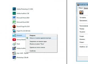
First, connect a voltmeter to the headphone output (Either to the right or to the left channel).

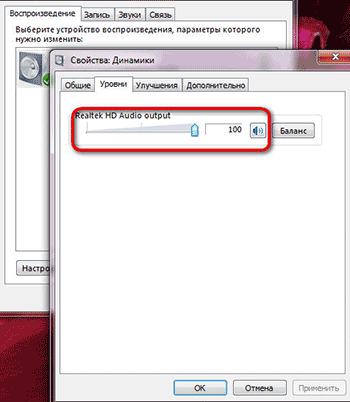
Turn off all sound effects and equalizers, open the speaker properties and set the volume level to 100%.
Open the program, press “Options”, in “Tone Interval” select “Frequency”, and set the step to 1Hz.

Close "Options", set the volume level to 100%, set the initial frequency to 10Hz and press "Play". With the “+” button, we begin smoothly, in 1 Hz steps, to increase the generator frequency to 500 Hz.

At the same time, we look at the voltage value on the voltmeter. If the maximum amplitude difference is within 2dB (1.259 times), then this sound card suitable for measuring speaker parameters. For me, for example, the maximum value was 624mV, and the minimum value was 568mV, 624/568 = 1.09859 (0.4dB), which is quite acceptable.
1.1.2. Let's move on to the long-awaited Thiel-Small parameters. The minimum parameters by which it is possible to calculate and design acoustic design (in this case subwoofer) is:
- Resonance frequency (Fs),
- Total electromechanical quality factor (Qts),
- Equivalent volume (Vas).
For a more professional calculation, you will need even more parameters, such as mechanical quality factor (Qms), electrical quality factor (Qes), sensitivity (SPL), etc.
1.1.2.1. Determining the resonant frequency (Fs) of a loudspeaker.
We collect such a scheme.


The speaker should be in free space as far as possible from the walls, floor and ceiling (I hung it from a chandelier). We open the NCH Tone Generator program again, insist on the volume as described above, set the initial frequency to 10Hz and begin to gradually increase the frequency in 1Hz steps. At the same time, we again look at the value of the voltmeter, which will first increase, reach the maximum point (Umax) at the natural resonance frequency (Fs), and begin to decrease to the minimum point (Umin). With a further increase in frequency, the voltage will gradually increase. The graph of the dependence of voltage (active resistance of the speaker) on the frequency of the signal looks like this.

The frequency at which the voltmeter value is maximum is the approximate resonant frequency (at a step of 1 Hz). To determine the exact resonant frequency, it is necessary in the region of the approximate resonant frequency to change the frequency in steps no longer by 1 Hz, but by 0.05 Hz (accuracy 0.05 Hz). We write down the resonant frequency (Fs), minimum value voltmeter (Umin), the value of the voltmeter at the resonant frequency (Umax) (in the future they will be useful for calculating the following parameters).
1.1.2.2.
Determination of the total electromechanical quality factor (Qts) of a loudspeaker.
Find UF1,F2 using the following formula.
![]()
By changing the frequency, we achieve the values of the voltmeter corresponding to the voltage UF1, F2. There will be two frequencies. One is below the resonant frequency (F1), the other is above (F2).

You can check the correctness of the calculations with this formula.
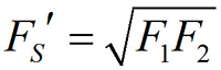
If the difference between Fs' and Fs does not exceed 1 Hz, then you can safely continue measurements. If not, then you need to do everything first. We find the mechanical quality factor (Qms) using this formula.

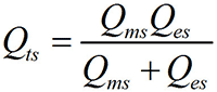
The electrical quality factor (Qes) is found using this formula.

Finally, we determine the total electromechanical quality factor (Qts) using this formula.
1.1.2.3. Determine the equivalent volume (Vas) of a loudspeaker.
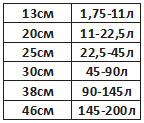
To determine the exact equivalent volume, we need a prefabricated, durable, sealed bass reflex box with a hole for our speaker.

The volume of the box depends on the diameter of the speaker, and is selected according to this table.
We fix the speaker to the box and connect it to the circuit described above (Fig. 9). Again, open the NCH Tone Generator program, set the initial frequency to 10Hz and use the “+” button to start smoothly, in 1Hz steps, to increase the generator frequency to 500Hz. At the same time, we look at the value of the voltmeter, which again begins to increase to the frequency FL, then decrease, reaching the minimum point at the frequency of the phase inverter (Fb), increase again and reach the maximum point at the frequency FH, then decrease and slowly increase again. The graph of the dependence of voltage on the frequency of the signal has the form of a two-humped camel.


And finally, we find the equivalent volume (Vas) using this formula (where Vb is the volume of the box with the phase inverter).

We repeat all our measurements 3-5 times and take the arithmetic mean of all parameters. For example, if we got the Fs values, respectively, 30.45Hz 30.75Hz 30.55Hz 30.6Hz 30.8Hz, then we take (30.45+30.75+30.55+30.6+30.8)/5= 30.63Hz.
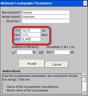
As a result of all my measurements, I received the following parameters for my speaker:
- Fs=30.75Hz
- Qts=0.365
- Vas=112.9≈113 L
1.2. Modeling and calculation of the subwoofer case (box) using the JBL Speakershop program.
There are several options for acoustic design, of which the following options are most common.
- Vented box-box with phase inverter,
- Band-pass 4th, 6th and 8th order,
- Passive radiator - a box with a passive radiator,
- Closed box - a closed box.

The type of acoustic design is selected based on the Thiel-Small parameters of the loudspeaker. If Fs/Qts<50, то такой громкоговоритель можно использовать исключительно в закрытом оформлении, если Fs/Qts>100, then exclusively in Vented box or Band-pass or Closed box. If 50
First, download and install the program. This program is written for Windows XP and does not work on Windows 7. To make the program work on Windows 7, you need to download and install virtual machine Windows Virtual PC-XP Mode (you can download it from the official Microsoft website), and run the installation of JBL Speakershop through it. You also need to open JBL Speakershop through a virtual machine. After opening the program, we see this interface.

Press "Loudspeaker" and select "Parameters--minimum", in open window write, respectively, the value of the resonant frequency (Fs), the value of the equivalent volume (Vas), the value of the total electromechanical quality factor (Qts) and press “Accept”.
At the same time, the program will offer two optimal (with the most even frequency response) options, one in a closed design (Closed box), the other in a Vented box (box with a phase inverter). Press “plot” (both in the Vented box and in the Closed box) and look at the frequency response graph. We choose the design, the frequency response of which is most suitable for our requirements.

In my case, this is the Vented box, because at low frequencies (20-50Hz), the Closed box has a much larger amplitude drop than the Vented box (Figure above).
If the volume of the box suits you optimally, then you can build a box with such a volume and enjoy the sound of the subwoofer. If not (with too large volumes), then you need to set your own volume (the closer to the optimal volume, the better) and calculate the optimal tuning frequency of the phase inverter.

To do this, in the Vented box area, click “Custom”, in the window that opens, write your volume of the box, click “Optimum Fb” (in this case, the program will calculate the optimal tuning frequency of the phase inverter, at which the frequency response of the acoustic design will be the most linear) and then “Accept”.

Press “Box” and select “Vent…”, in the window that opens, in the “Custom” area, write the diameter of the pipe (Dv), which we will use as a phase inverter. If we use two phase inverters, then we put a dot on “Area” and write the total cross-sectional area of \u200b\u200bthe pipes.


Press “Accept” and in the “Custom” area on the line Lv the length of the phase inverter pipe will appear. Now that we know the internal volume of the box, the diameter and length of the phase inverter pipe, we can safely proceed to the design of the acoustic design, however, if you really want to know the optimal aspect ratio of the box, you can press “Box”, select “Dimensions…”.

1.3. Designing the case (box) of the subwoofer
To obtain high-quality sound, it is necessary not only to correctly calculate, but also carefully manufacture the acoustic design case. After determining the internal volume of the box, the length and diameter of the phase inverter pipe, you can safely proceed to the manufacture of the subwoofer case. The material of the box must be sufficiently strong and rigid. The most suitable material for high power acoustic enclosures is 20 mm MDF. The walls of the box are attached to each other with self-tapping screws, and the gaps between them are smeared with sealant or silicone. After the box is made, holes are made for the handles, and the outer surface is finished. All irregularities are leveled with putty or epoxy (I add a little PVA glue to the putty, which prevents cracks from appearing over time and reduces the level of vibrations). After the putty dries, the surfaces must be sanded until perfectly smooth walls are obtained. The finished box can be either painted or covered with a self-adhesive decorative film, or simply glued on with a thick fabric. From the inside, a sound-absorbing material consisting of cotton wool and gauze is glued to the walls of the box (in my case, I glued the batting). As a phase inverter, you can use a plastic sewer pipe or a paper rod from different rolls, as well as a ready-made phase inverter that can be bought at almost any music store.
Frame active subwoofer consists of two compartments. The loudspeaker itself is located in the first compartment, and the entire electrical part (signal conditioner, amplifier, power supply ......) is located in the second. In my case, I placed the adder unit and the filter unit in a separate compartment from the power amplifier unit, power supply unit and cooling unit. From the inside, I glued foil to the walls of the compartment of the adder unit and the filter unit, which I connected to ground (GND). The foil prevents external fields and reduces noise levels.


If you use my printed circuit boards, then these compartments should have the following dimensions.


2. The electrical part of the active subwoofer
Let's move on to the electrical part of the active subwoofer. The general scheme and principle of operation of the device is represented by this scheme.

The device consists of four blocks assembled on separate printed circuit boards.
- Adder block (Summators),
- Filter unit (Subwoofer driver),
- Power amplifier block,
- Power supply (Power supply) and cooling unit (Heatsink fun).
First, the audio signal enters the Summators block, where the signals of the right and left channels are summed. Then it enters the filter unit (Subwoofer driver), where the subwoofer signal is formed, which includes a volume control, subsonic filter (low-pass filter), bass booster (increase in volume at a certain frequency) and Crossover (filter low frequencies). After formation, the signal enters the power amplifier unit (Power amplifier), and then to the loudspeaker.
We will discuss these blocks separately.
2.1. Block of adders (Summators)
2.1.1.Scheme
First, consider the adder circuit shown in the figure below.

Sound signal with external devices(computer, CD player……..) goes to the adder block, which has 6 stereo inputs. 5 of them are ordinary line inputs, differing from each other only in the type of connector. And the sixth is a high-voltage input, to which you can connect the speaker output (for example, music Center or car radio that do not have a line-out). Each input has a separate op amp combiner that shifts the right and left channel signals, which prevents the sound signal from one external device to another, while allowing you to connect several external devices to the subwoofer at the same time. And there are also outputs (5 outputs, the 6th simply did not fit on the board, and therefore did not install), which make it possible to apply the same signal that enters the subwoofer to the input of a broadband stereo system. This is very convenient when the sound source has only one output.


2.1.2.Components
TL074 (5 pcs.) were used as operational amplifiers. Resistors are rated for 0.25W or higher (resistance ratings are shown in the diagram). All electrolytic capacitors have a voltage rating of 25 volts or higher (capacitance ratings are shown in the diagram). As non-polar capacitors, you can use ceramic or film capacitors (film is better), but if you really want to, you can put special audio capacitors (capacitors designed for use in high-quality audio systems). Chokes in the power supply circuit of operational amplifiers are designed to suppress the “noise” coming from the power supply. Coils L1-L4 contain 20 turns wound with copper wire with a diameter of 0.7mm, on the core of a gel pen (3mm). RCA, 3.5mm audio jack, 6.35mm audio jack, XLR, WP-8 connectors are also used.

2.1.3.Printed circuit board


The printed circuit board is made according to . After soldering the parts, the printed circuit board should be coated to avoid oxidation of the copper.
2.1.4. Photo of the finished adder block


The adder unit is powered by a bipolar ±12V power supply. The input impedance is 33kΩ.
2.2 Filter block (Subwoofer driver)
2.2.1.Scheme
Consider the subwoofer driver circuit shown in the figure below.

The summed signal from the adder block enters the filter block, which consists of the following parts:
- Volume control (volume regulator),
- Infra low pass filter (subsonic filter),
- Bass amplifier of a certain frequency (bass booster),
- Low pass filter (crossover).
Volume control takes place at two levels. The first is when the signal enters the filter block, which reduces the level of the own “noise” of the adder block, the second, when the signal leaves the filter block, which reduces the level of the own “noise” of the filter block. The volume is adjusted using a variable resistor VR3. After the first level of volume control, the signal enters the so-called “bass booster”, which is a device that increases the amplitude of signals of a certain frequency. That is, if the bass booster tuning frequency is inserted, for example, at 44Hz, and the gain level is at 14dB, then the frequency response looks like this ( Row1).

Row2- tuning frequency=44Hz, gain level=9dB,
Row3- tuning frequency=44Hz, gain level=2dB,
Row4- tuning frequency=33Hz, gain level=3dB,
Row5- tuning frequency=61Hz, gain level=6dB.
The tuning frequency of the bass booster is inserted using a variable resistor VR5 (within 25 ... 125Hz), and the gain level with a resistor VR4 (within 0 ... + 14dB). After the bass booster, the signal enters the subsonic filter, which is a filter that cuts off unwanted, ultra-low signals that are no longer audible to humans, but can severely overload the amplifier, thereby reducing the actual output power of the system. The cutoff frequency of the filter is adjusted using a variable resistor VR2 within 10…80Hz. If, for example, the cutoff frequency is inserted at 25Hz, then the frequency response has the following form.

After the infra-low pass filter, the signal enters the low-pass filter (crossover), which cuts off the upper, unnecessary for the subwoofer (mid + high) frequencies. The cutoff frequency is adjusted using a variable resistor VR1 within 30 ... 250 Hz. The slope of the attenuation is 12 dB / octave. The frequency response has this form (at a cutoff frequency of 70 Hz).

2.2.2.Components
TL074 (2pcs), TL072 (1pc) and NE5532 (1pc) were used as operational amplifiers. Resistors are rated for 0.25W or higher (resistance ratings are shown in the diagram). All electrolytic capacitors have a voltage rating of 25 volts or higher (capacitance ratings are shown in the diagram). As non-polar capacitors, ceramic or film capacitors (preferably film ones) can be used. Chokes in the power supply circuit of operational amplifiers are designed to suppress the “noise” coming from the power supply. Three double (50kOhm-2pcs, 20kOhm-1pcs) and two quad variable (50kOhm-6pcs) resistors are also used. Two dual resistors can be used as quad variable resistors.
2.2.3.Printed circuit board

PCB files in *.lay and *.pdf format can be downloaded at the end of the article.
2.2.4. Photo of the finished filter unit


The filter unit is powered by a bipolar ±12V power supply.
2.3. Block power amplifier (Power amplifier).
2.3.1.Scheme
An Anthony Holton amplifier with field-effect transistors in the output stage is used as a power amplifier. There are a lot of articles describing the principle of operation, assembly and tuning of the amplifier on the Internet. Therefore, I will limit myself to embedding the schematic and my version of the PCB.

2.3.2.Printed circuit board
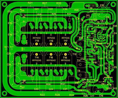


PCB files in *.lay and *.pdf format can be downloaded at the end of the article. The power amplifier unit is powered by a bipolar power supply with a voltage of ± 50 ... 63V. The output power of the amplifier depends on the supply voltage and the number of pairs field effect transistors(IRFP240+IRFP9240) in the output stage.
2.4. Power supply and cooling unit (Power supply)
2.4.1.Scheme

2.4.2.Components
As a power transformer, you can use both a ready-made and a home-made transformer with a power of approximately 200W. The voltages of the secondary windings are shown in the diagram.


The diode bridge Br2 is designed for a current of 25A. Capacitors C1 ... C12, C29 ... C31 must have a rated voltage of 25V. Capacitors C13…C28 must have a nominal voltage of 63V (when the supply voltage is below 60V), or 100V (when the supply voltage is above 60V). As non-polar capacitors, it is better to use film capacitors. All resistors are rated at 0.25W. The R5 thermistor is smeared with thermal paste and attached to the amplifier heatsink. The operating voltage of the fan is 12V.
2.4.3.Printed circuit board

PCB files in *.lay and *.pdf format can be downloaded at the end of the article.
3. The final stage of subwoofer assembly


List of radio elements
| Designation | Type | Denomination | Quantity | Note | Score | My notepad | |
|---|---|---|---|---|---|---|---|
| U1-U5 | Operational amplifier | TL074 | 5 | To notepad | |||
| C1-C4, C15, C16, C25-C27, C29, C39-C42 | 10 uF | 14 | To notepad | ||||
| C5-C10, C23, C24, C28, C30, C35-C38 | Capacitor | 33 pF | 14 | To notepad | |||
| C11-C14, C19-C22, C31-C34 | Capacitor | 0.1uF | 12 | To notepad | |||
| C17, C18 | electrolytic capacitor | 470uF | 2 | To notepad | |||
| R1, R2 | Resistor | 390 ohm | 2 | To notepad | |||
| R3, R12 | Resistor | 15 kOhm | 2 | To notepad | |||
| R4, R16-R18 | Resistor | 20 kOhm | 4 | To notepad | |||
| R5, R13-R15 | Resistor | 13 kOhm | 4 | To notepad | |||
| R6, R10, R23, R24, R31, R33, R40, R41, R46, R47 | Resistor | 68 kOhm | 10 | To notepad | |||
| R7, R11, R21, R22, R32, R34, R37, R38, R45, R48 | Resistor | 22 kOhm | 10 | To notepad | |||
| R8, R9, R25, R26, R29, R30, R39, R42, R49, R50 | Resistor | 10 kOhm | 10 | To notepad | |||
| R19, R20, R27, R28, R35, R36, R43, R44 | Resistor | 22 ohm | 8 | To notepad | |||
| L1-L4 | Inductor | 20x3mm | 4 | 20 turns, wire 0.7mm, rim 3mm | To notepad | ||
| L5-L13 | Inductor | 100 mH | 10 | To notepad | |||
| Filter block | |||||||
| U1 | Operational amplifier | TL072 | 1 | To notepad | |||
| U2, U4 | Operational amplifier | TL074 | 2 | To notepad | |||
| U3 | Operational amplifier | NE5532 | 1 | To notepad | |||
| C1-C5, C7-C10, C15-C17, C20, C23 | Capacitor | 0.1uF | 14 | To notepad | |||
| C6 | Capacitor | 15 nF | 1 | To notepad | |||
| C11-C14 | Capacitor | 0.33uF | 4 | To notepad | |||
| C21, C22 | Capacitor | 82 nF | 2 | To notepad | |||
| VR1-VR3, VR5 | Variable resistor | 50 kOhm | 4 | To notepad | |||
| VR4 | Variable resistor | 20 kOhm | 1 | To notepad | |||
| R1, R3, R4, R6 | Resistor | 6.8 kOhm | 4 | To notepad | |||
| R2, R10, R11, R13, R14 | Resistor | 4.7 kOhm | 5 | To notepad | |||
| R5, R8 | Resistor | 10 kOhm | 2 | To notepad | |||
| R7, R9 | Resistor | 18 kOhm | 2 | To notepad | |||
| R12, R15-R17, R20, R22, R26, R27 | Resistor | 2 kOhm | 8 | To notepad | |||
| R18, R25 | Resistor | 3.6 kOhm | 2 | To notepad | |||
| R19, R21 | Resistor | 1.5 kOhm | 2 | To notepad | |||
| R23, R24, R30, R31, R33 | Resistor | 20 kOhm | 5 | To notepad | |||
| R28 | Resistor | 13 kOhm | 1 | To notepad | |||
| R29 | Resistor | 36 kOhm | 1 | To notepad | |||
| R32 | Resistor | 75 kOhm | 1 | To notepad | |||
| R34, R35 | Resistor | 15 kOhm | 2 | To notepad | |||
| L1-L8 | Inductor | 100 mH | 1 | To notepad | |||
| Power amplifier block | |||||||
| T1-T4 | bipolar transistor | 2N5551 | 4 | To notepad | |||
| T5, T9, T11, T12 | bipolar transistor | MJE340 | 4 | To notepad | |||
| T7, T8, T10 | bipolar transistor | MJE350 | 3 | To notepad | |||
| T13, T15, T17 | MOSFET transistor | IRFP240 | 3 | To notepad | |||
| T14, T16, T18 | MOSFET transistor | IRFP9240 | 3 | To notepad | |||
| D1, D2, D5, D7 | rectifier diode | 1N4148 | 4 | To notepad | |||
| D3, D4, D6 | zener diode | 1N4742 | 3 | To notepad | |||
| D8, D9 | rectifier diode | 1N4007 | 2 | ||||
Many are interested in using an electronic transformer as a power supply for a bass amplifier and making such a cheap "amplifier" for a home subwoofer.
The board for such a device was developed in one hour.
It is a combination of a low-frequency power amplifier (approximately 70-100 W), a low-pass filter for a subwoofer to give out only pure bass without other music, an adder for combining signals from stereo channels into one single one, and a switching power supply so that the entire device could work directly from a 220 V network without the use of additional devices.
It turned out to be a small amplifier with great potential.
Let's start with the fact that the amplifier is single-channel, operates in class AB and is built on the ultra-legendary TDA7294 chip, providing an output power of 70 pure watts. For a home subwoofer, this is more than enough.
The binding for this chip is pretty standard.
The power supply is the most common electronic transformer. A 105W Taschibra transformer was used.
It was completely disassembled and reassembled on a common board. The secondary winding of the power transformer has been rewound. The native one gave out 12 V of output voltage, while the new one began to give out bipolar 28 V.
The network winding consists of 85 turns of wire 0.5 mm thick. The secondary winding was wound with a twist, the total diameter of which is 1.2-1.5 mm. It consists of 40 turns with a tap from the middle.
The mains and secondary windings must be isolated from each other. For winding, it is possible to use a W-shaped core. It will be even more convenient for insulating the windings.
The board turned out to be very compact, despite the fact that it housed 3 separate parts of the system, not counting the passive adder.
Power transistors of the MJE13007 series in the TO220 package are installed on a common heat sink along with a power amplifier chip. All power components in the face of a microcircuit and transistors must be insulated from the heat sink. Thermal paste won't hurt either.
The board does not have acoustic protection from "permanent" in case the amplifier burns out. There is no protection on the power supply. If desired, you can install without problems. The absence of protection does not mean that the circuit is unreliable. If you do not close anything, then everything will work for a very long time. In some car amplifiers industrial production also lacks protection - and nothing!
A fairly standard second-order filter circuit is also used to filter the signal, providing a cutoff of 100 Hz.
The circuit is based on the cheap and popular BA4558 chip. This is a dual operational amplifier, which has found wide application in audio technology.
The power supply of the filter is unipolar. The supply voltage is around 15 V. The resistor in the power circuit provides current suppression. It must be 2 watt.
It is desirable to install the microcircuit on a DIP-8 type socket.
As mentioned earlier, the filter provides a cutoff of the order of 100 Hz, that is, all frequencies that are higher will be absent. If desired, you can make the cutoff frequency lower.
To combine the signals from both channels before the filter, a simple passive adder circuit is used.
A properly assembled circuit does not need to be adjusted. Everything should work right away.
When assembling, pay attention to the presence of two jumpers.

After the assembly is completed, it is highly recommended to check the functionality of the individual parts. First, the power supply is checked (the filter and amplifier are turned off in advance). If everything is in order with the unit, then the amplifier is connected and its operation is checked. And at the end, you can already connect and check the low-pass filter. On the board, the pins of the microcircuits are numbered.
So, the main question about the possibility of using electronic transformers to power amplifiers has finally been answered. Yes it is possible. Even without any modifications, although the use of a surge protector at the input of an electronic transformer, as well as a smoothing electrolyte after the bridge, will only benefit. Chokes after the output bridge would not interfere either. But by ear, no difference in sound was found.
Attached files:
Homemade connector for LCD displays
Every car owner knows that good audio systems are quite expensive. The price of just one of the main elements that allow you to produce high-quality sound - an amplifier - can be more than a hundred dollars. Therefore, many connoisseurs of high-quality sound are thinking about how to make a musical amplifier for a subwoofer with their own hands. We will talk about this below.
[ Hide ]
Tools and materials
If you decide to equip your car with a quality 12 volt radio, you will need a subwoofer and an amplifier to ensure good sound.
The output transistors must be provided with cooling, to do this, the elements can be bent to the board, while their contacts must be located upwards. After that, it is necessary to apply thermal paste on the contact surfaces and put a dielectric film, and only then radiators are mounted on top. Thanks to this, you can slightly reduce the dimensions of the latter and, in general, save space in the case.
Since the installation of a subwoofer involves the use of an amplifier for a car, it will be necessary to isolate the low frequency range from the incoming pulse. The scheme itself is a single-channel one, so it is necessary to put a channel adder at the input to the pulse processing device. This will convert a two-channel pulse into a single-channel one.
As for the rectification and switching device, this device consists of several components:
- A switching device necessary to notify the driver about the readiness or unavailability of the amplifier for work. The notification is carried out thanks to two diodes - red and green.
- rectifier device. This device is necessary to stabilize the pulses that are transmitted to the main control unit.
Before you make an amplifier for a 12 volt subwoofer, you need to prepare one of the main components of the device - the case. Of course, this element is needed, otherwise where to install the circuit? Alternatively, the case can be built with your own hands from plywood or purchased ready-made, it all depends on your capabilities and preferences. For example, an amplifier can be connected to the case from a DVD player. Such a device has a small size, usually a stylish design, and its connectors, if necessary, can be redesigned to connect to car subwoofers.
A better option would be to use an aluminum and, most importantly, a whole body, which can also serve as a radiator. As you know, during operation, the circuits heat up, as a result of which, when using a wooden case in the manufacture, you will have to think through the cooling system. Moreover, this system should be of the highest quality. Moreover, in some cases it is even necessary to do active cooling. Therefore, the use of an aluminum case is the best option (the author of the video is AKA KASYAN).
Manufacturing instructions
The amplifier for can be assembled after preparing all the main elements. A 12 volt device can be easily assembled by connecting all the components and placing them in the case. Due to the voltage of the conversion device (transformer), a small fan can be placed on the device case. Thanks to him, the air flow will be circulated in the system, which will allow to cool the circuits and protect them from overheating, respectively, premature failure.
When connecting with a block, it is necessary to use wires in cambric. If the wires come into contact with each other, this can lead not only to the formation of a short circuit, but also to the burnout of the constituent elements in principle. The units must be installed in the case in such a way that airflow can circulate freely between these components. The circuit must be fixed as firmly as possible, otherwise the 12-volt amplifier made will rattle while driving and when the subwoofer is running.
Conclusion
During work, be careful - if you make mistakes, the blocks can fail. Take on this venture only if you have basic skills in the field of electronics. If you have never dealt with such tasks before, then it is better to entrust this matter to specialists.
Sorry, there are currently no surveys available.
Video "Making an amplifier at home"
The process of making an amp at home is presented in the video below (the author of the video is Ivan Aponasenko).
The design is implemented on a single compact board. Monoblock consists of 3 parts:
LF amplifier, LF filter, voltage converter. The first two parts are described in the article “ How to make a simple home subwoofer amplifier”.
The harness has the same components, only the printed circuit board pattern has been slightly changed. In this design, instead of a network power supply, there is a voltage converter, since there is only 12V in the vehicle's on-board network, and the amplifier needs a 2-polar power source of 30-35V. You should not apply higher, so as not to burn the microcircuit, although according to the documentation the allowable voltage is up to 40V.
Device Diagram:

Amplifier power 100W. This is enough to rock the dynamic head of the 75GDN-1 type, which is popular with home-made people.
Let us analyze the voltage converter in more detail, it is because of it that many novice radio amateurs do not risk assembling high-power amplifiers.
This is a 2-stroke push-pull boost converter. The master oscillator is built on the TL494. It is followed by a direct conduction transistor driver, which discharges the gate capacitance of the field-effect transistors after they are closed. As you know, if a certain voltage is applied to the gate of a field-effect transistor (in this case, this is a control pulse), then it will open. And if you then remove the gate voltage, the transistor will still remain open. Therefore, some circuits are supplemented with a separate driver, which must close the transistor in time.
Although many specialized PWM controllers have a fairly powerful output stage for this purpose, the TL494 is not one of them. You can use any p-n-p transistors in the driver, our KT3107 are perfect. Field-effect transistors N-channel IRFZ44, although others are possible. They must be selected so that the calculated key voltage is at least 40V, and the current is at least 30A (ideally 60V and 50-60A). My transformer is wound on an Epcos N8 core. The calculation was made according to the program.
The primary winding has 2 x 5 turns, wound with a bundle of 5 wires with a diameter of 0.7mm. Secondary - 11 turns, 6 wires 0.33mm each. Of course, for each core, different winding data will be obtained, so the calculation must be made for your own ferrite.
The no-load current (XX) of the inverter turned out to be no more than 50mA, with a connected filter and an amplifier of about 250mA (without an input signal). The minimum current XX largely depends on the operating frequency. I tuned the oscillator to 168 kHz, the core is good, so there were no problems. In the case of Soviet cores of the 2000NM brand and the like, I do not advise raising the frequency above 60 kHz.
The output diodes of the UF5408 are ultra-fast at 3A, heat up but do not overheat. The inductors at the input and output are not critical, removed from a computer power supply. They can be replaced with jumpers. Unfortunately, I did not find output smoothing capacitors of the required capacity, therefore, in a prototype in 2 arms, they differ by a couple of hundred microfarads.
A monoblock amplifier of this type can be built into any passive subwoofer. Just don't forget the heat sink. The amplifier works in class AB and the radiator needs a fairly large one. Be sure to isolate the cases of field-effect transistors and amplifier microcircuits from the radiator using heat-conducting gaskets and insulating washers. I installed microcircuits in DIP packages on sockets, but it's still better to solder on the board, because. with constant vibration in the car, they may eventually lose contact with the socket.
To check the performance, the signal was given with mobile phone, i.e. about 30% of the maximum power of the amplifier is involved. In order to shoot more, the input signal must come from the car radio. Speaker from a Chinese 50W subwoofer with a resistance of 4 ohms. By the way, the power transistors of the inverter do not heat up at low power, so I took a chance to start it without a radiator.